|
|
#11 |
 Join Date: May 2011
Location: Sydney, Australia
Posts: 2,466
|
Before you start going crazy and buying equipment and parts plug your front speakers into your rear outlets and see if they work.
|
|
|

|
|
|
#12 | |
 Join Date: Feb 2011
Location: San Marcos CA
Posts: 1,786
|
Quote:
I do not own a 90 corvette so I don't exactly know what the wiring harnesses look like, but I heard they are compatible if you solder the wires from the original amplifiers. |
|
|
|

|
|
|
#13 | |
|
Join Date: May 2013
Location: France
Posts: 55
|
Quote:
cvette98pacecar; great idea i didn't thought of that i will try to put the front speaker in the back and the back in the front next we to see what's going on 
|
|
|
|

|
|
|
#14 | |
 Join Date: Jan 2009
Location: Portland Oregon metro area (Washington side)
Posts: 3,193
|
Quote:
You do have some sort of power to the front but it may not be going where it should, thus the tac tac tac sound. If your going to swap speakers rather than measure a few voltages then I'd swap a single know good rear one to the front not the suspect front one to the rear since that is the one you modified. You could avoid damaging the rear pre-amp depending on what the wiring error is (if there is one) in the front one.
__________________
Scott Vett owner since 1979._It's about the car and the people |
|
|
|

|
|
|
#15 |
|
Join Date: May 2013
Location: France
Posts: 55
|
Thanks everyone for your help
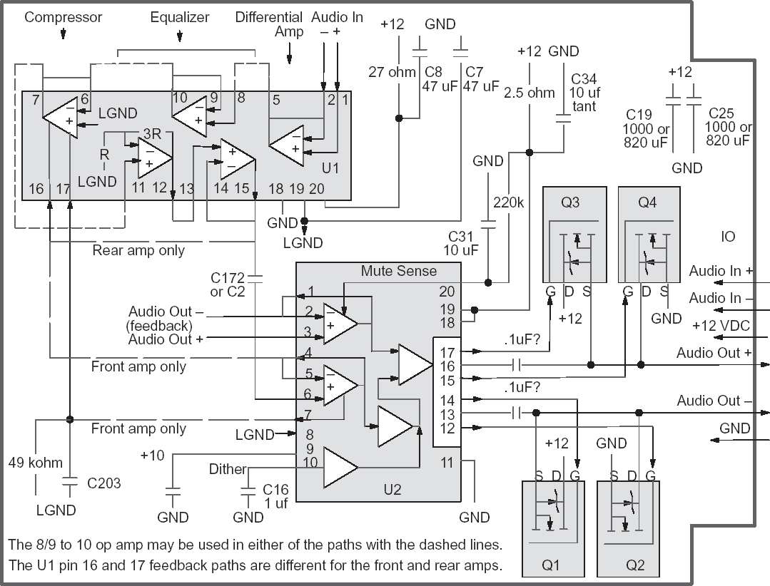
i unmount the amplifier again and use this schema to see what's going on  as you said, the wire are differently on late 90 amplifier and early 90 the audio out and +12V are inverted i've changed the wire and now it works !  Thanks again 
Last edited by DarkAngel; 01-18-2014 at 04:09 PM. |
|
|

|
|
|
#16 | |
 Join Date: Jan 2009
Location: Portland Oregon metro area (Washington side)
Posts: 3,193
|
Quote:
I'm very glad all worked out for you. Now you can test the volume control that is connected to the fuel peddle. The louder you want the music the more you need to accelerate
__________________
Scott Vett owner since 1979._It's about the car and the people |
|
|
|

|
|
|
#17 | |
|
Join Date: Dec 2012
Location: NC
Posts: 1,783
|
What is this schematic?
There are no Right Channel grounds represented? Is this the Bose Head Unit? There are 3 separate logic boards in the Bose Head Unit. Is this the Mainboard of the 3? I have a partial Bose Head Unit Schematic here: http://www.zr1.net/forum/showthread.php?t=19620 Quote:
|
|
|
|

|
|
|
#18 |
 Join Date: Feb 2011
Location: San Marcos CA
Posts: 1,786
|
It is the speaker amp schematic.
|
|
|

|
|
|
#19 |
|
Join Date: Dec 2012
Location: NC
Posts: 1,783
|
|
|
|

|
|
|
#20 |
 Join Date: Feb 2011
Location: San Marcos CA
Posts: 1,786
|
The schematic isn't complete, but there is tuned L/C on the board- which is more or less tuned to the speaker size. You can't do anything with these except repair them. It's a lot more economical to go aftermarket if everything on the bose has gone bad (there's a tuner box separate or the head unit, then the 4 amps driving proprietary 1 ohm speakers).
As you have no doubt seen on other links to posts, the Nissan units are newer improved versions of the late c4 amps and are a dime-a-dozen and are a cheap way to keep the factory unit going if you like the oem look. |
|
|

|
 |
|
|