
|
 01-21-2013
|
#31 |
|
Join Date: Dec 2012
Location: NC
Posts: 1,783
|
So here's the DD circuits:
power, ground, of course, and Input, which comes from a tap / splice, on socket 29. And number 29, is one of the 2 'Output Shaft Speed' leads. You guys knew that tho', didn'tcha??? And note the crappy connections for Input and Output. IS THAT THE SOURCE OF THE SPEEDO FLUCTUATION AT IDLE?????  and the tap splice for DD Input:  DD Output, brown to orange  and orange, splice to a yellow, near the back of the tranny: (and $20 says that yellow, which is going into an existing harness, is the speedo feed, to the ECM??? 
|

|

|
|
01-21-2013
|
#32 |
|
Join Date: May 2007
Location: Chicagoland, IL
Posts: 9,683
|
There's no Sensor Ground which is NOT the same as Ground which is for Power. The VSS sensor is looking for ground.
What wretched electrical work!    Last edited by XfireZ51; 01-21-2013 at 04:20 PM. |
|
|
|
|
01-21-2013
|
#33 |
|
Join Date: Dec 2012
Location: NC
Posts: 1,783
|
Thanks for the words of encouragement there buddy!
True tho', and this truth hurts!!! So the speedo signal path, in sum: Shaft Speedo Output, from tranny signal generator, TO controller module, INTERCEPTED by DD splice / tap, INTO DD, OUT, to OEM yellow lead. I cannot follow this yellow lead harness, as it rises behind driver's cylinder head. I will find VSS input at ECM, which hopefully is yellow, and do continuity to the DD output. And IIRC, '94 VSS is yellow (or purple) ? And remember, speedo is functioning, except for fluctuation from 0 - to 30, 50, 40, and back... So before I attempt to make better connections at the DD, the question is, why did they even put it in? Why can I not use the TCU speedo output? Should I try wiring in the TCU speedo output, while I have the DD disconnected? Last edited by Schrade; 01-21-2013 at 04:56 PM. |
|
|
|
|
01-21-2013
|
#34 |
|
Join Date: May 2007
Location: Chicagoland, IL
Posts: 9,683
|
I'm willing to bet that the fluctuation is due to the fact the VSS sensor doesn't have a solid signal ground. Its probably jumping to the power ground. I had this happen once when TPS sensor was connected to my WB so I could see TPS% as part of WB O2 datalog. Worked great until one day it didn't. TPS was all over the place. Needless to say motor ran like crap. Until I removed the TPS signal from the WB and then everything worked. I was using power ground for the signal ground. Didn't like that. Needs to be separate which is why ECM has separate sensor grounds from power grounds. Each sensor needs a reference ground along w reference signal. Some sensors may share.
|
|
|
|
|
01-21-2013
|
#35 | ||
|
Join Date: Dec 2012
Location: NC
Posts: 1,783
|
Quote:
VSS (as now wired), doesn't have a dedicated ground? Or the DD needs another ground? Or just 2 better connections? (which I'm about to do) Do I need to trace the leads from the VSS, from the case connector??? Quote:
|
||
|
|
|
|
01-21-2013
|
#36 |
|
Join Date: May 2007
Location: Chicagoland, IL
Posts: 9,683
|
Heres a good thread from CF. Altho this is for an OBDII PCM, the idea is the same. You can see were Pin A31 and A32 are for VSS Ground and VSS Signal. The DD unit takes that signal from the trans and translates into something that our ECM will understand. The micro switch settings on the unit are for that purpose.
Here's an interesting post from this thread: "If 85-89 used a 2k pulse per mile VSS, there must be a typo in the 89 service manual. It shows a block diagram lower right corner that the VSS is 4k pulses per mile. If he needs to correct the VSS frequency so it can be used on the 87 Dash Cluster he can use an electronic ratio adapter. If the wires are connected, I would think he would get some kind of reading on the display even if the frequency was off. Something similar to the Dakota Digital's SGI-5 may work. The SGI-5 can convert a sine wave from 4K to 2K but the converted output signal does not appear from their description to be a sine wave. You would need to contact them to see if it would work." Here's the thread. http://forums.c**f**m.com/c4-tech-pe...gnal-help.html 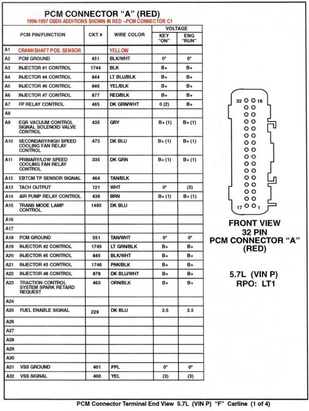
|
|
|
|
|
01-21-2013
|
#37 | |
|
Join Date: Dec 2012
Location: NC
Posts: 1,783
|
Alright - copy on this post fully Sir.
Quote:
But what's missing (or cross wired) in my wiring? Is it as simple as getting a line to ground, at the DD, where it says 'Signal Ground'? |
|
|
|
|
|
01-21-2013
|
#38 |
|
Join Date: Dec 2012
Location: NC
Posts: 1,783
|
Took a ride, and the speedo is still jumping around from 0, while stopped, even after re-connecting the previous connections. Simple spring clamp connectors, like your stereo speakers. They had a strand or 2 in the clamp.
Theirs:  Mine:  Didn't really matter... At speed, it shows in perfect sync with the handheld. And handheld still hangs at "Turn Key Off For 10 Seconds To Save Changes". Comm Error. Speedo seemed to behave for a few minutes after startup. Closed Loop might be energizing a circuit that causes speedo interference??? Last edited by Schrade; 01-21-2013 at 07:18 PM. |
|
|
|
|
01-21-2013
|
#39 |
|
Join Date: Dec 2012
Location: NC
Posts: 1,783
|
Maybe got a lead on the fluctuation at 0...

|
|
|
|
|
01-22-2013
|
#40 | |||
|
Join Date: Dec 2012
Location: NC
Posts: 1,783
|
Quote:
Signal Ground terminal, FROM DD to [a ground]. Will TRY that tomorrow - hope a little Global Warming comes in... Quote:
And I guess that only a jumper wire is necessary for the clutch pedal Cruise kill switch? Quote:
Dave; I don't know if the speedo drive is magnetic or what (will have to wait for small claims decision for paperwork, or info from tranny maker (RPM Transmission). |
|||
|
|
|
 |
|
|


 Linear Mode

