|
|
#171 |
 Join Date: Mar 2007
Location: Crystal Lake, IL
Posts: 7,194
|
Well many of you thought I threw the towel in but not yet, I am just riding out a rough time as I am in the dog house as I try to finalize a purchase of my 2nd Z(Don't ask its been a PITA..and its not done). I began to dissamble the heads and will post pics today.
I sent the timing chain cover to Jerry so he could fab some gaskets, and as a plug to Jerry word on the streets is that his gaskets are quicly becoming the standard. I will walk through removing the cams, etc then I need to get new pistons, liners from Polo-1 and new gaksets and then I will hopefully finish the shortblock this summer.....I have cancelled plans to build and long block as I need to sell off some stuff to cover the purchase of my 2nd Z. I anticipate the shortblock will go in 90 #966 and not my lower mile 92 #234. Anywhoo pics coming with info....hope this is useful LGAFF 92 ZR1 #234 Last edited by LGAFF; 01-04-2009 at 08:21 PM. |
|
|

|
|
|
#172 |
 Join Date: Mar 2007
Location: Crystal Lake, IL
Posts: 7,194
|
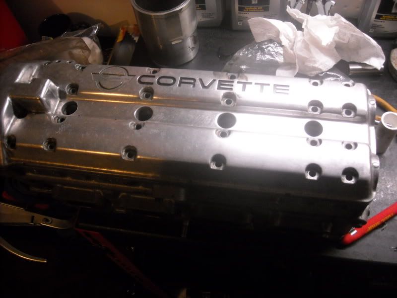
Here the the head.....obviously first step would be to remove cam cover bolts..
 Shot with the cam cover removed and cams exposed: Notice the cam hold downs, these are soley to hold the cams is place and from what I understand not a true bearing surface. Underneath the front hold downs is a thrust bearing which looks like it helps keep the cam from walking(maybe someone can shed more light on its purpose.) 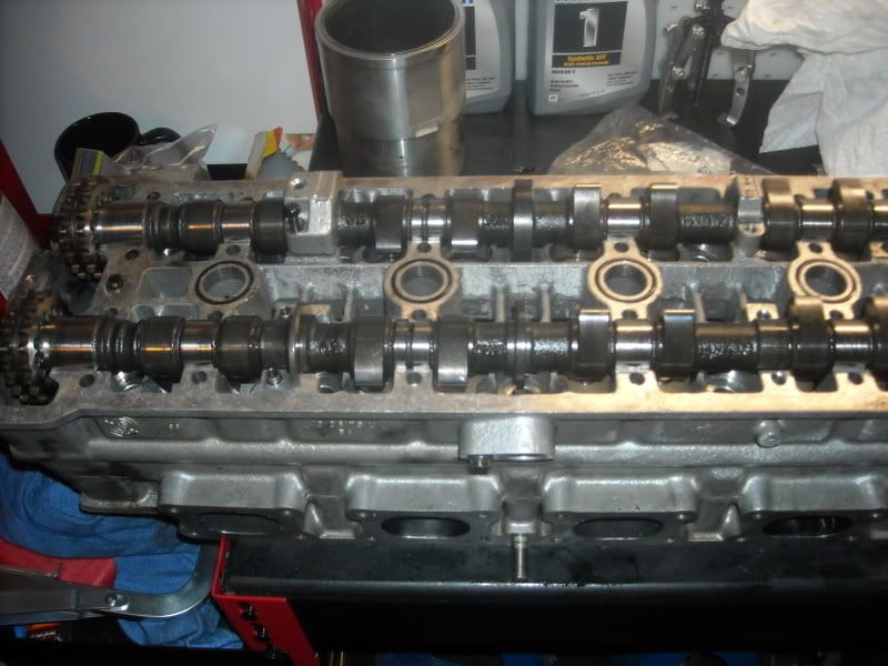 Cam plug/Seal: These are the rubber plugs you can see at the end of the ends, 4 per head.... 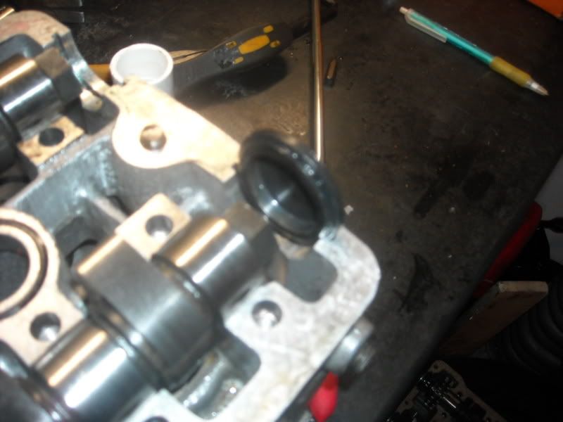
Last edited by LGAFF; 01-04-2009 at 11:27 PM. |
|
|

|
|
|
#173 |
 Join Date: Mar 2007
Location: Crystal Lake, IL
Posts: 7,194
|
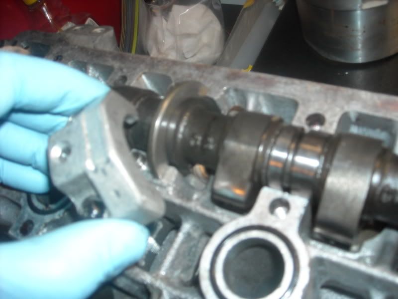 Here is a shot of the thrust bearing under the cam hold down. Here is a shot of the thrust bearing under the cam hold down.Below are pics of the reluctor for the Cam position sensor; someone can fill in more detail but the basics are that the position sensor is magnetic, and the slot disrupts the signal and this is what tells the engine the position and RPM of the cam. 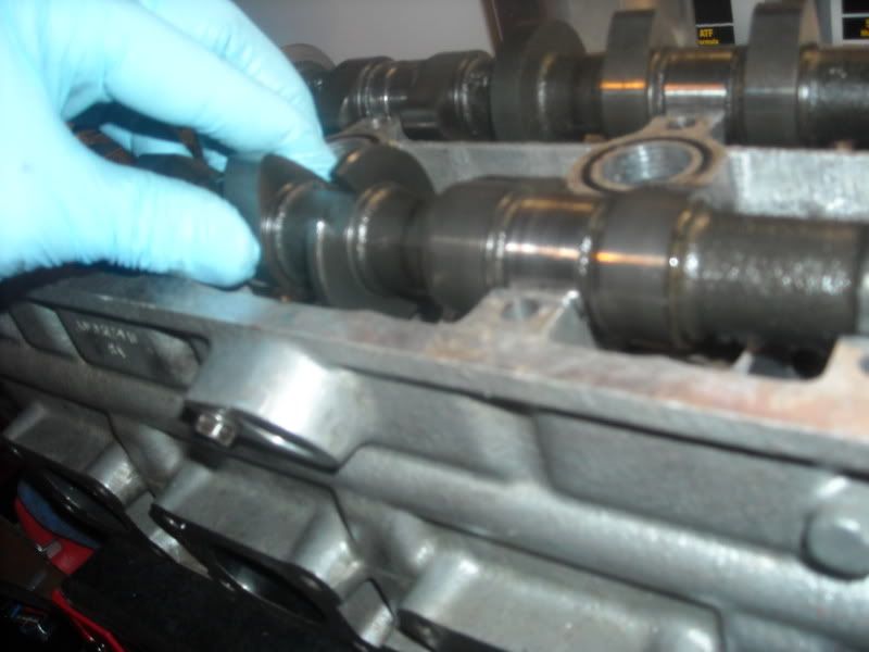 Below is a shot of the front of the cam, as you can see the gear is pinned at the top, there are plate before and after the gear when the pin is put in place it locks in the position of the gear. 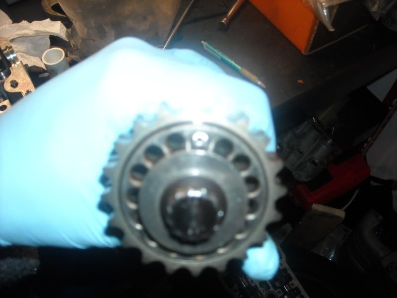
Last edited by LGAFF; 01-04-2009 at 11:26 PM. |
|
|

|
|
|
#174 |
 Join Date: Dec 2003
Location: Chicagoland,IL
Posts: 2,679
|
Lee,the front cam caps have the thrust bearing in them.
I would be careful trying to pull the cams down with those little caps and screws. Pete
__________________
'91 #1635 PoloGreen 350 LT5 11.09 @ 129.27 11.04 @ 128.86 474RWHP 400RWTQ http://www.youtube.com/watch?v=SFNFOhGGlR4 http://www.youtube.com/watch?v=ZlRIOMwaDYY https://sites.google.com/site/peteszr1garage |
|
|

|
|
|
#175 |
 Join Date: Mar 2007
Location: Crystal Lake, IL
Posts: 7,194
|
Underneath each cam lobe is a lifter, here is a picture of the lifter from a side shot.....the part that rides the cam is flat..
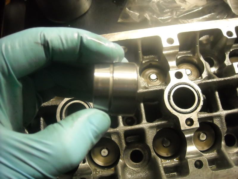 The bottom rides rides on the valve stem tip, here is a shot of the bottom, of the lifter on the left, to the right you can see the top of the valve spring: 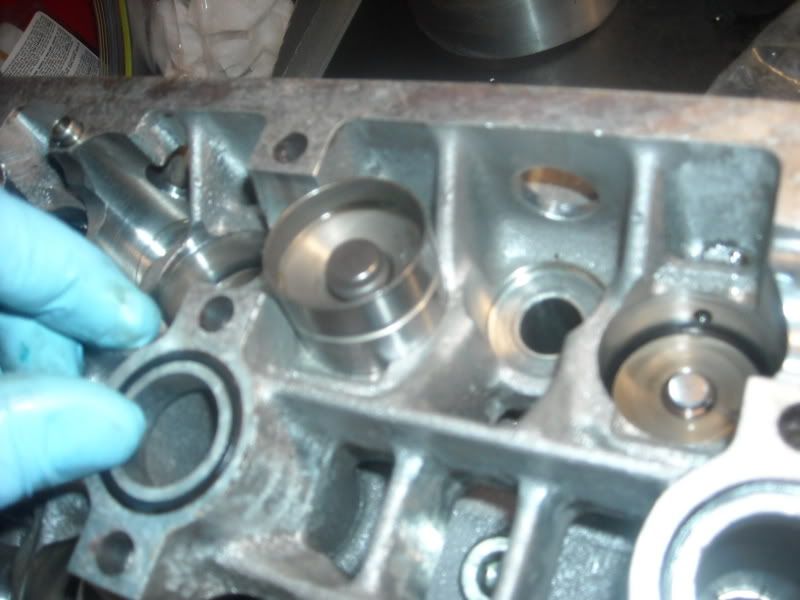
|
|
|

|
|
|
#176 |
 Join Date: Mar 2007
Location: Crystal Lake, IL
Posts: 7,194
|
The valve spring is held in place with a cap, in the center there are two retaining clips which creat an interference when the lock into the top of the stem itself. There are actually two springs, and inner and outer, belwo is a shot fo the cap, springs.
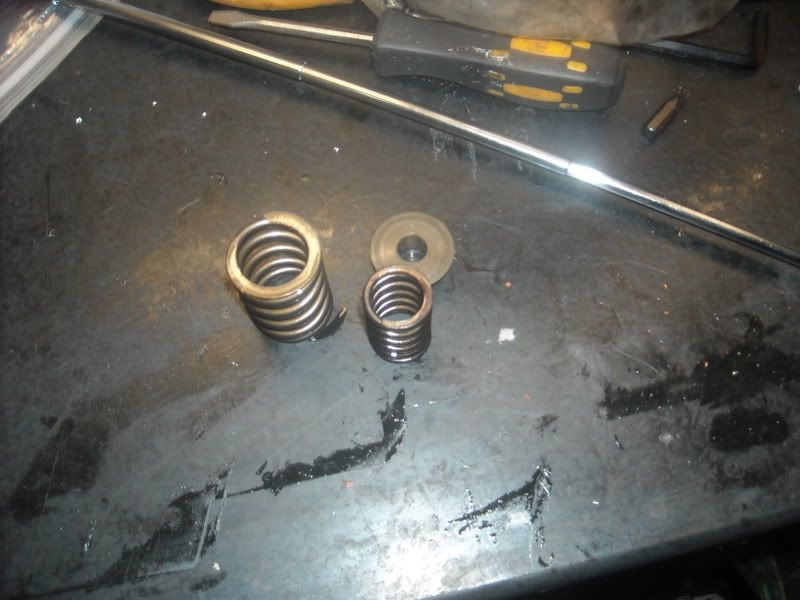 Pics of retainers on the end of a telescoping magnet: 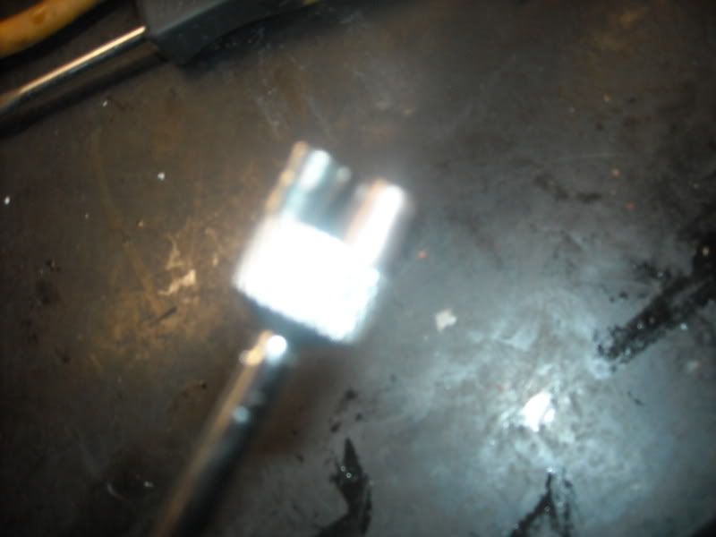 In order to remove the spring, you need a spring compressor as pictured below: The top part of the compressor which looks like a pick presses against the valve face, the bottom of the compressor uses an attachment to push on the outside fo the valve spring cap. This allows you remove the retainers and release the tool allowing you to take out the valve 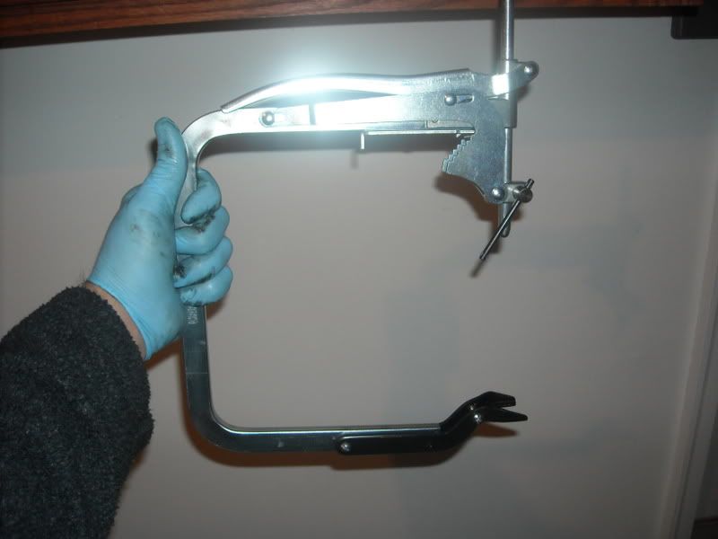
Last edited by LGAFF; 01-04-2009 at 08:49 PM. |
|
|

|
|
|
#177 |
 Join Date: Mar 2007
Location: Crystal Lake, IL
Posts: 7,194
|
I did not have the tool adapter which presses on the outside of the valve spring cap.....so on phrogs advice I went to Home Depot, bought a 1" PCV pipe fitment, and used it....
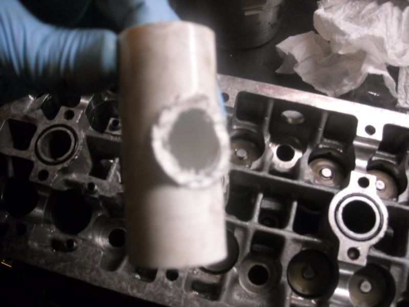 Pic of PCV attachment being put in place over the valve stem cap: 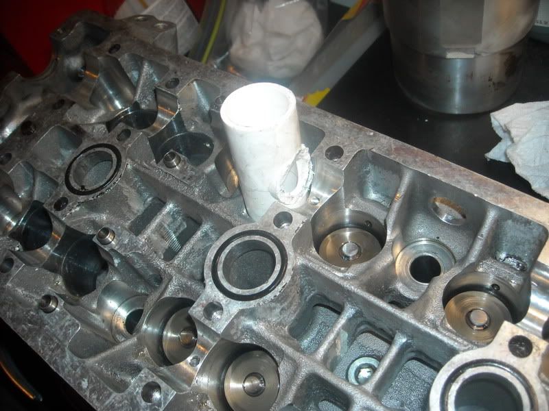 Pic of tool in place: 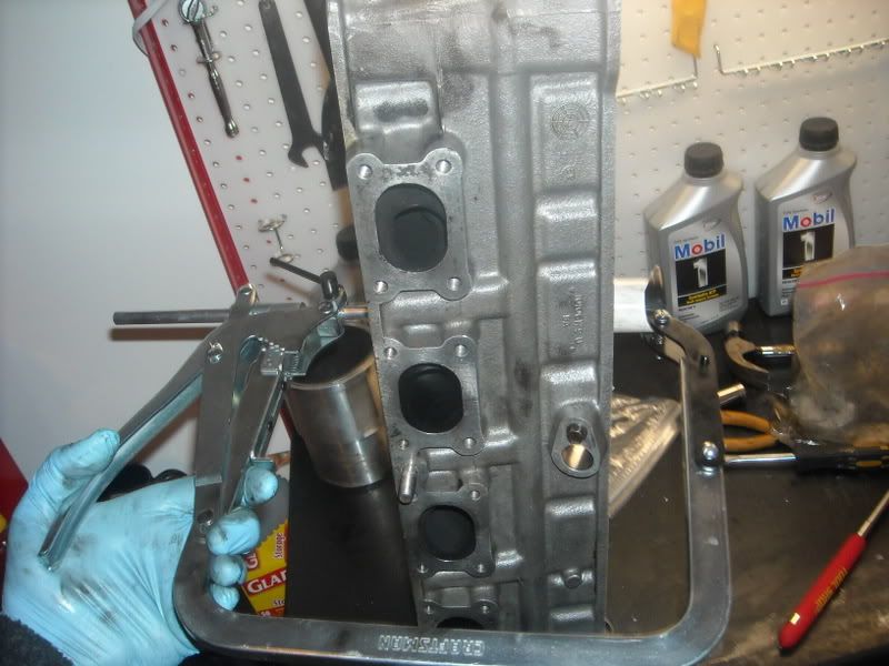
Last edited by LGAFF; 01-04-2009 at 08:56 PM. |
|
|

|
|
|
#178 |
 Join Date: Mar 2007
Location: Crystal Lake, IL
Posts: 7,194
|
Once the tool is in place, use a telescopic magent to remove the retainers...shot of valve cap from inside the compressor adapter: You can see the retainers, one is place one that has falen out.
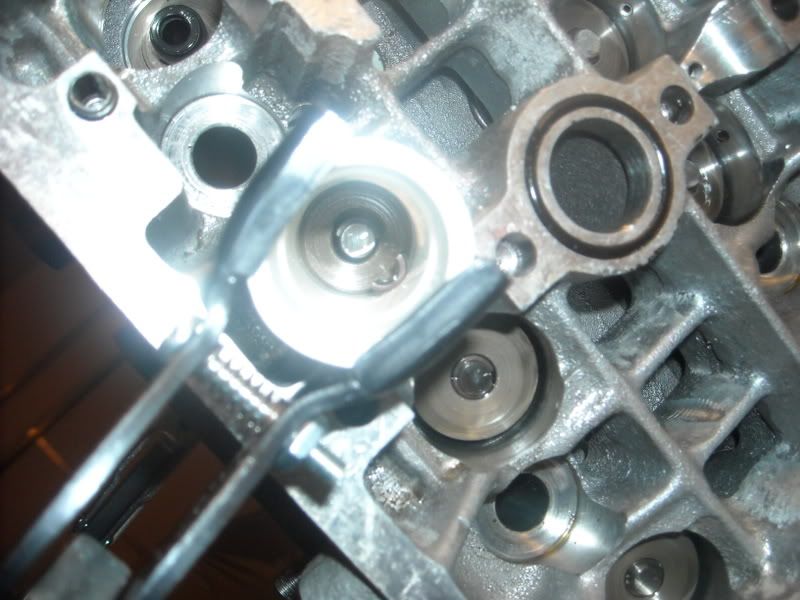 Once done place the valves in order: 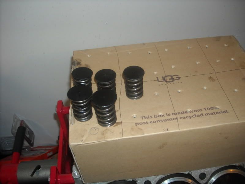
|
|
|

|
|
|
#179 |
 Join Date: Mar 2007
Location: Crystal Lake, IL
Posts: 7,194
|
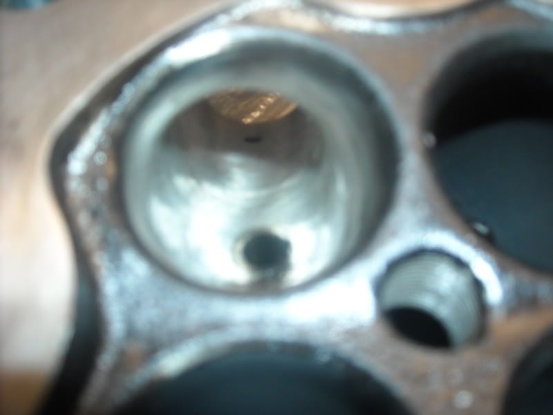
Pic of the porting on the heads in the bowl:
|
|
|

|
|
|
#180 |
|
Join Date: Oct 2005
Location: Candy Apple...yUmMy
Posts: 1,137
|
You should never use a magnet on your internal engine components......trapping unwanted metalic dust formed from the cam and rings lapping in during break-in on your valve train is not good, but its your motor.
|
|
|

|
 |
| Thread Tools | |
| Display Modes | |
|
|