|
|
#1 |
 Join Date: May 2010
Location: Japan
Posts: 3,104
|
Well, since I had some down time while waiting on a cylinder head, I started upgrading all my exterior bulbs (will do interior soon) while I was installing euro taillights, etc. and decided to upgrade the back up bulbs to 50W units. While doing my research to do 50W or LED/SMD, etc. I remember the tech article written by Steve Jasik and had bought the Radio Shack relay years ago so now was the time to install it.
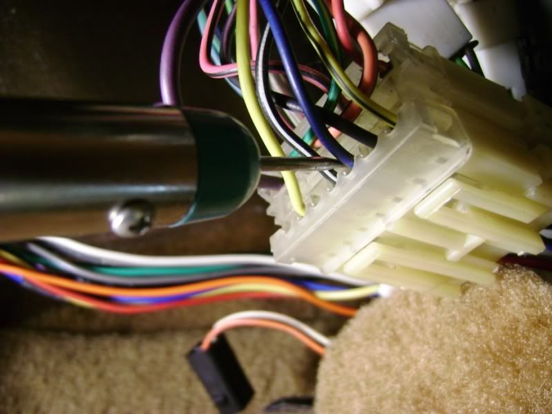
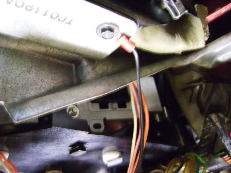
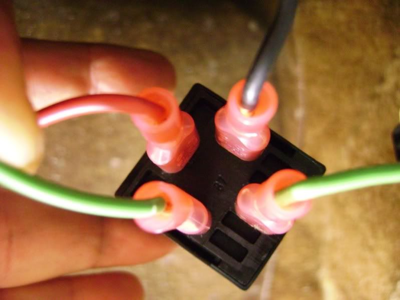
http://www.zr1netregistry.com/Inform...ht-Switch.aspx Steve Jasik was kind enough to attempt to explain this to me further, but being the novice automotive electrician that I am, I wanted to learn more before messing around with this project and get a true understanding. I decided to buy a great book that I would highly recommend to any novice that wants to get involved with automotive electronics. Automotive Wiring and Electrical Systems by Tony Candela. This guy is a genius in my eyes and also very nice and responsive to my questions, taking the time as an author to reply to a commoner. The book is very well written and has quality illustrations: http://www.amazon.com/Automotive-Wir...9539134&sr=8-1 Well, moving on to the project I enlisted his help to clarify in more detail as I am a visual person and wanted to make sure I knew what I was doing. My most serious project of electrical on the Z was making a harness for my euro lights and battery relocation. Tony sent me the attached illustration after I provided pages from the electrical service manual so there would be no doubt so I decided to share it. So I assume no responsibility for anyone wanting to do this and assume that you have a basic understanding as well as all the instructions that are already mention by Steve are omitted and my purpose is just to show what would have helped me visually being an amateur.  Using Gordon's Killebrew's wireless circuit tester I confirmed the wires I needed to use for this project and here is the dark blue wire from the harness as decribed by Steve and tested with ignition, reverse and fuse to confirm. I bought this from Gordon in 2006 when I went to his school as a sole student and was sold watching him use it even thought it felt weird to use my own body as ground. I really love this tool and sure does beat using my VOM or circuit tester that I have to ground; one of my favorite tools next to my Snap On Techangle torque wrenches.  Here is the light green wiring being confirm with same type of testing in reverse, ignition, fuse pull.  Here is the ground connection made right under the fuse box to the brace.  Here is a picture tapping into the blue wire and I highly recommend using blue wire. I did not have any and decided in my mind that I know that is my hot wire anyway so it made sense to me.  So here is the end result where the ground wire is connected to terminal 85, light green wire is cut and split to terminal 30 and 86 and the dark blue wire tapped connected to terminal 87.
__________________
Craig "ZR-1 NO KA 'OI" "ZR-1 ICHIBAN" 1995 #228 Black/Black with Dunn Heads ZR-1 owner since September 2003 ZR-1 Net Registry Founding Member #0074 NCM Lifetime Member #2048 
Last edited by HAWAIIZR-1; 10-03-2021 at 02:54 PM. Reason: Update link |
|
|

|
|
|