Great write up Paul....but I do have a question 
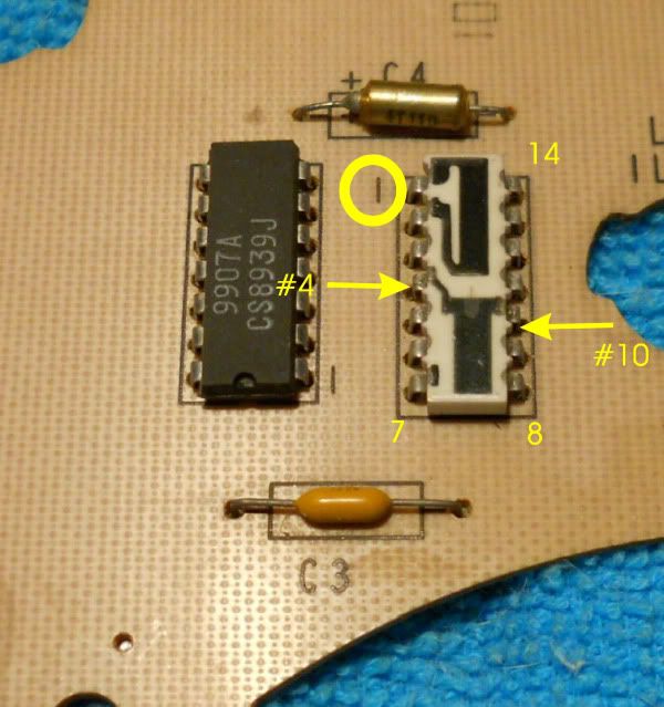
I think Paul replaced the suspect resistor on the Dash Circuit Board (Resister across Capacitor C4) with a 240K Ohm resistor to get the Tachometer Calibration correct. Some say 220 K Ohm is the standard resistance in that chip (#4 to #10).
It appears Paul was correcting a circuitry that did Drift with Time and the Drift in Resistance possibly do to deteriorating original chip resistance (#4 to #10) and capacitor deterioriation.
What was the resistor in the chip (#4 to #10) that came on the board in the first place? Was it 220 K Ohms?
It seems that one might get very close to a correct Tachometer reading just replacing that chip resistor (#4 to #10) with a resister of 220K Ohms in parallel with the Capacitor C4 (soldering on either side of the circuit board)?
Quote:
Originally Posted by Paul Workman

ZR-1 Tachometer Calibration
Hope this helps!
P.
copyright 2012 All rights reserved
|
It appears that Paul was correcting a deterioration error in the original Chip Resistor (chip #4 to #10) and Capacitor C4 deterioration and ghikal was correcting a major deterioration in the standard Chip Resistor (#4 to #10) only.
Quote:
Originally Posted by ghlkal
Just to follow up now that I can read the RPM from the HVAC display. Here's how far off my tach is:
tach reads / actual RPM
1000 / 650
3000 / 1750
4000 / 2325
4500 / 2700
5000 / 2975
6000 / 3500
This is up to a 70% error  |