
|
 01-03-2014
|
#11 |
  Join Date: Aug 2009
Location: South Dakota/California
Posts: 3,788
|
Post 10 - ZR1 Engine (LT5) ZR-1 Lubrication Simplified Post 1. -SOLUTIONS- Overview and Ebay Searches Post 2. ZR1 General Post 3. ZR1 Electrical Post 4. ZR1 Engine Post 5. ZR1 Drive Train Post 6. ZR1 Engine Fuel, Lubrication, Cooling, and Exhaust Post 7. ZR1 Specifications, Restorations, Air, Audio, Lifts, and Road Trips Post 8. ZR1 Engine (LT5) Bolts and Hydraulics Post 9. ZR-1 ALDL and associated Codes Post 10. ZR-1 Lubrication Simplified Last UPDATE of post 11 Dec, 2018 Last edited by Dynomite; 10-07-2018 at 01:22 PM. |

|

|
|
01-03-2014
|
#12 |
 Join Date: May 2013
Location: Beaver, PA
Posts: 516
|
Wow. You da man. Very helpful.
|
|
|
|
|
01-25-2014
|
#13 |
|
Join Date: Aug 2009
Location: South Dakota/California
Posts: 3,788
|
The Oil Filter Adapter has many important functions. The Oil Filter Adapter is NOT for the sole purpose of holding/adapting the Oil Filter.
The oil paths through the Oil Filter Adapter Housing are describe in Item #5 below. 1. A Discussion of the Functions of the Oil Filter Adapter. a. Control Oil Temperature. See Related ECM Code #52 Item #3 ZR1 ECM CODES 1990 TO 1992 b. Provide Sensor Feedback to the Instrument Panel. c. Provide Oil Filtration. d. Assure proper Oil Flow at any Oil Temperature. e. Assure proper Oil Flow with contaminated Oil Filters. The Oil Pressure Regulating Valve situated between the Oil Pump and Oil Filter Adapter controls and maintains Consistent Oil Pressure. As an aside 2. Oil Pressure Sensor (Dash Gauge) Malfunction I changed out the oil pressure sensor for the dash gauge (top of oil filter) after engine installation. Oil pressure cold was registering 75 lbs. After changing out the oil pressure sensor, oil pressure is registering 55 lbs steady hot or cold and does not increase much with revs. Oil Filter Adapter Sensors ..............................................Oil Filter Adapter Ports and Sensors 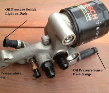  3. LT5 Oil Pressure and Oil Temperature Regulation a. The Oil Pressure Regulation Valve (OPRV) (just after oil pump) opening pressure is 50-60 psi. 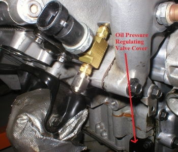  b. The Oil Cooler Bypass Valve on the Oil Filter Adapter allows oil to bypass the open oil cooler at hot temperatures since oil cooler is a bit restrictive. This valve raises the pressure a bit on the flow trying to bypass the oil cooler making sure some oil does go through the oil cooler. c. The Oil Temperature Control Valve on oil filter housing opens oil flow from the oil cooler. The temperature opening characteristics of this valve are Thermostat-Open-203 degree F, Fully open-266 degree F. d. The Oil Filter Bypass Valve on oil filter housing allows oil to bypass oil filter if the oil filter becomes to restrictive. e. Oil pressure is always available to the Oil Cooler Bypass Valve. Oil flows from the oil pump (past the OPRV) to the oil filter through the Oil cooler and through the Oil Cooler Bypass Valve or directly through the Oil Temperature Control valve when the oil temperature is below 203 deg F. The oil cooler flow return and Oil Cooler Bypass Valve are open at the same time. The oil flow from the oil cooler is never totally blocked (half moon cutout of shuttle valve). The Oil pump flow at Idle is 1.6 gpm and the Oil pump flow at 7,000 rpm is 9.1 gpm. 4. Oil Filter Adapter Functional Details Oil Temperature Control Valve Assembly.....................Oil Temperature Valve Thermostat opens at 203 deg F  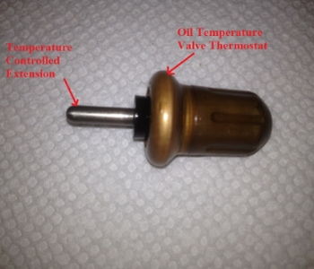 Continued Next Page Last UPDATE of post 13 Dec, 2018 Last edited by Dynomite; 01-09-2019 at 07:55 PM. |
|
|
|
|
01-25-2014
|
#14 |
|
Join Date: Aug 2009
Location: South Dakota/California
Posts: 3,788
|
Oil Temperature Shuttle Valve Open (HOT)............................Oil Termperature Shuttle Valve Closed (COLD)
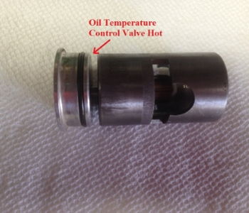  Oil Cooler Bypass Valve Inside..................................................Oil Cooler Bypass Valve Outside This valve raises the pressure a bit on the flow trying to bypass the oil cooler making sure some oil does go through the oil cooler. 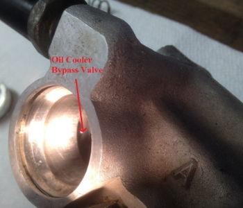 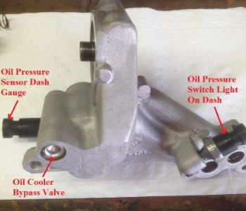 Oil Temperature Control Valve Compensation..............Oil Filter Adapter (Oil Temperature Valve Housing) The orifice allows the valve to move without being hydraulically locked in place.   5. Oil Flow Paths. COLD - Oil Temperature Less than 203 deg F. a. The Oil is pushed up from the bottom Port on the Oil Filter Adapter Housing past the TOP Oil Cooler Port which is ALWAYS OPEN. b. The Oil then is pushed through the Top Opening of the Oil Temperature Control Valve to the bottom of the Temperature Control Valve Port. c. The Oil is also pushed against the Oil Cooler Bypass Valve which it will not open since the path through the Temperature Control Valve Port is Open. d. Some Oil flows through the Oil Cooler back into the Bottom Oil Cooler Port since the Bottom of the Temperature Control Valve has a Half Moon Port that is Always Open. e. The Oil then pushed up through the Oil Filter Outside Diameter and also against the Oil FIlter Bypass Valve just in case the Oil Filter is too Restrictive. d. The Oil is then pushed out the center Oil Filter Adapter Fitting (M20x1.5) past the Oil Pressure Sensor for Dash Gauge, past the Oil Temperature Sensor, and past the Oil Pressure Switch Light on Dash Sensor out the Top of the Bottom Ports of the Oil Filter Housing Adapter to the Crankshaft and Top End Camshafts. The Oil pressurizes and lubricates the Timing Chain Tensioners and Timing Chains as the oil flows. See Timing Chain Idler Sprocket Lubrication and Installation WARM - Oil Temperature greater than 203 deg F but less than 266 deg F. a. The direct Oil Path to the Oil Filter through the Oil Temperature Control Valve is not yet closed but is becoming Restrictive. b. The Bottom Port of the Oil Temperature Control Valve is Opening beyond the Half Moon Port. c. The Oil Path around the Oil Temperature Control Valve through the Oil Cooler Bypass Valve may come into play. d. The Oil is then pushed out the center Oil Filter Adapter Fitting (M20x1.5) past the Oil Pressure Sensor for Dash Gauge, past the Oil Temperature Sensor, and past the Oil Pressure Switch Light on Dash Sensor out the Top of the Bottom Ports of the Oil Filter Housing Adapter to the Crankshaft and Top End Camshafts. The Oil pressurizes and lubricates the Timing Chain Tensioners and Timing Chains as the oil flows. See Timing Chain Idler Sprocket Lubrication and Installation HOT - Oil Temperature greater than 266 deg F. a. The Top of the Oil Temperature Control Valve Port Through the Oil Temperature Control Valve is now completely Closed. b. All Oil is directed through the Oil Cooler (Top Oil Cooler Port) or through the Oil Cooler Bypass Valve around (outside) the top of the Oil Temperature Control Valve. c. The Bottom of the Oil Temperature Control Valve Port is now completely open allowing Oil to go from the Oil Cooler through the bottom of the Oil Temperature Control Valve directly to the Oil Filter and Oil Filter Bypass Valve. d. Some Oil passing through the Oil Cooler Bypass Valve will flow directly to the Oil Filter and Oil Filter Bypass Valve depending on the Restrictions to Oil Flow through the Oil Cooler. e. The Oil is then pushed out the center Oil Filter Adapter Fitting (M20x1.5) past the Oil Pressure Sensor for Dash Gauge, past the Oil Temperature Sensor, and past the Oil Pressure Switch Light on Dash Sensor out the Top of the Bottom Ports of the Oil Filter Housing Adapter to the Crankshaft and Top End Camshafts. The Oil pressurizes and lubricates the Timing Chain Tensioners and Timing Chains as the oil flows. See Timing Chain Idler Sprocket Lubrication and Installation 6. There IS an Oil Level Sensor on the 91'-95' ZR-1 Oil Pan. The Oil Pan for 1990, 91 & 92 are interchangable with the only difference being, the 1990 LT5 engine was not equipped with a Low Oil Level Sensor. The extra material was cast into the pan but not machined for the screw-in sensor. As such, the oil level indicator would not be functional if the 1990 oil pan is used for 1991 & 1992 applications Oil Level Sensor TIPS Brass Oil Level Sensor 93'-95' Jerrys Brass Oil Level Sensor 93' to 95' 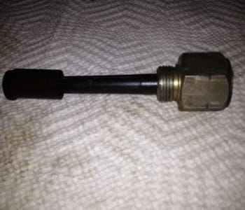  Plastic oil Level Sensor 91'-92' Summit Racing Oil Level Sensor Jerrys Plastic Oil Level Sensor  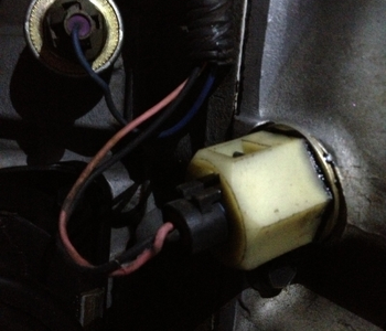 Last UPDATE of post 14 Dec, 2018 Last edited by Dynomite; 10-07-2018 at 01:20 PM. |
|
|
|
|
01-25-2014
|
#15 |
|
Join Date: Aug 2009
Location: South Dakota/California
Posts: 3,788
|
Reserved
Last edited by Dynomite; 04-01-2018 at 10:20 PM. |
|
|
|
|
05-09-2014
|
#16 |
|
Join Date: Aug 2009
Location: South Dakota/California
Posts: 3,788
|
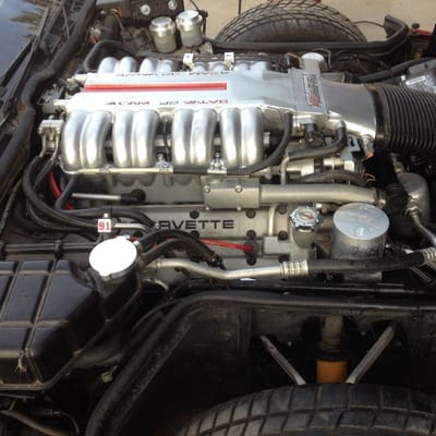
Creating Albums and Hosting Post Photos TIPS
Post 131 - Resizing Photos for Forum Posts and Creating Reference Links 1. This photos were resized on my computer using PAINT. 2. Then the photos were uploaded to my Registry Albums on this Forum. 3. I then clicked on one photo and copied the BB Code which is posted as [IM G]http://www.zr1.net/forum/picture.php?albumid=211&pictureid=3063[/IMG] 4. I left a space between the M and G so the photo would not show Just showing what you can do with Album Photos using Paint on your computer before you upload to your Albums on this Forum. Stumbled on something very interesting  The photo below is from my Album on the Other Forum. On the Other Forum I can post the photos above that are in my Album on This Forum. Last UPDATE of post 16 Feb, 2017 Last edited by Dynomite; 02-01-2017 at 08:54 PM. |
|
|
|
|
05-09-2014
|
#17 |
|
Join Date: Aug 2009
Location: South Dakota/California
Posts: 3,788
|
Reserved
Last edited by Dynomite; 10-07-2018 at 01:23 PM. |
|
|
|
|
05-09-2014
|
#18 |
|
Join Date: Aug 2009
Location: South Dakota/California
Posts: 3,788
|
Assembly Line Diagnostic Link (ALDL) Fault Codes
1. ZR1 ECM CODES 1990 TO 1992 Code #12: Normal No Codes. Code #13: Left Oxygen Sensor Circuit. Code #14: Coolant Temperature Sensor Circuit High. Code #15: Coolant Temperature Sensor Circuit Low. Code #16: Direct Ignition System (DIS) Fault Line Circuit Code #21: Throttle Position Sensor Circuit High. Code #22: Throttle Position Sensor Circuit Low. Code #23: Manifold Air Temperature Sensor Circuit Low. Code #24: Vehicle Speed Sensor Circuit. Code #25: Manifold Air Temperature Sensor Circuit High. Code #31: Camshaft Sensor Circuit. Code #33: Manifold Absolute Pressure Sensor Circuit High - Low Vacuum. Code #34: Manifold Absolute Pressure Sensor Circuit Low - High Vacuum. Code #36: Direct Ignition System (DIS) Circuit (missing or extra EST signal) Code #41: Cylinder Select Error (Faulty or Incorrect Mem-Cal) Code #42: Electronic Spark Timing (EST) Circuit. Code# 43: Electronic Spark Control (ESC) Circuit. Code #44: Left Oxygen Sensor Circuit Lean. Code #45: Left Oxygen Sensor Circuit Rich. Code #46: Vehicle Anti-Theft System (VATS)(PASS-Key) Circuit. Code #51: Mem-Cal Error. Code #52: Engine Oil Temperature Sensor Circuit Low. Code #53: System Voltage. Code #54: Fuel Pump Circuit (Low Voltage) Code #55: System Voltage Code #56: Vacuum Sensor Circuit. Code #61: Secondary Port Throttle Valve System. Code #62: Engine Oil Temperature Sensor Circuit High. Code #63: Right Oxygen Sensor Circuit Open. Code #64: Right Oxygen Sensor Circuit Lean. Code #65: Right Oxygen Sensor Circuit Rich 2. ECM Related Explanations. 31 LCD Data Circuit-Circuit shorted to battery voltage or CCM driver open 33 Data Clock Circuit-Circuit shorted to battery voltage or CCM driver open 35 Data Strobe Circuit-Circuit shorted to battery voltage or CCM driver open 37 M Clock Circuit-Circuit shorted to battery voltage or CCM driver open 72 LCD Dimming Open Circuit-Circuit open or shorted to ground (radio & Climate control) H History code. May be intermittant. Code 31, 33, 35 related to the circuit from the CCM to the Instrument panel LCD. CCM 74 is also a lighting circuit problem. CCM 41 is loss of communication with the ECM. 3. ZR1 ABS Code - Definition 1990 Service Manual: (* = Requires Tech 1 Daignostic Tool) 12 - Diagnostic System Operational 21 - RF Wheel Speed Sensor Fault 22 - RF Toothed Wheel Frequency Error 25 - LF Wheel Speed Sensor Fault 26 - LF Toothed Wheel Frequency Error 31 - RR Wheel Speed Sensor Fault 32 - RR Toothed Wheel Frequency Error 35 - LR Wheel Speed Sensor Fault 36 - LR Toothed Wheel Frequency Error 41* - RF Solenoid Valve Fault 45* - LF Solenoid Valve Fault 55* - Rear Solenoid Valve Fault 61* - Pump Motor or Motor Relay Fault 63* - Solenoid Valve Relay Fault 71 - EBCM Fault 72 - Serial Data Link Fault 75 - Lateral Accelerometer Fault (Short to B+ or Ground, or Open Circuit) 76 - Lateral Accelerometer Fault (Signal Out of Range or Incorrect) Clearing Codes The fault codes in the EBCM's memory are erased in one of three ways: 1. Diagnostic Enable Line Procedure 2. Tech 1 "Clear Codes" Selection 3. Igniton Cycle Default Whichever method is used, be sure to verify proper system operation and absence of codes when clearing procedure is completed. 4. ZR1 Ride Control (SRC) Codes. 12 = Start of sequence 13 = Left rear time out 14 = Right Front time out 21 = Left Front time out 22 = Right Rear time out 31 = Left Front out of position 32 = Right Front out of position 33 = Left Rear out of position 34 = Right Rear out of position Out of position codes are triggered if the computer senses that the actuator has not found the end stop position on the shock. Remove actuator at the indicated shock. Turn the valve gear on the shock stops after about 3 / 4 of turn, then you have a bad actuator. If it spins around continuously then it is a bad shock 41 = Selective ride control switch short to voltage 42 = Selective ride control switch open contacts You can have a code 42 if you leave the switch in between indented positions 43 = selective ride control switch circuit open. 23 = If you start the car more than 3 times and do not move the car this code will set. Drive 3-6 feet and the light will go out. The ride control controller is located in the bin behind the drivers seat mounted with the ABS controller. 5. ZR-1 CCM Codes Code Definition 1.1 DISPLAY CCM fault codes 12 On-board diagnostics no codes (this is a good thing: no problem found) 13 DIC switches open or shorted to battery 14 DIC switches shorted to ground 16 Ignition 3 fuse circuit open 21 Horn relay coil shorted to battery or CCM internal open circuit 22 Rear defogger relay coil shorted to battery or CCM internal open circuit 24 Courtesy lamp relay coil shorted to battery or CCM internal open circuit 25 Courtesy lamp relay coil circuit open or shorted to ground 26 LCD blanking control circuit shorted to battery or CCM internal open 27 LCD blanking control circuit open or shorted to ground 31 LCD data circuit shorted to battery or CCM internal open 32 LCD data circuit open or shorted to ground 33 Data clock circuit shorted to battery or CCM internal open circuit 34 Data clock circuit open or shorted to ground 35 Data strobe circuit shorted to battery or CCM internal open circuit 36 Data strobe circuit open or shorted to ground 37 M clock circuit shorted to battery or CCM internal open circuit 38 M clock circuit open or shorted to ground 41 Loss of ECM serial data communications 51 Pass-key invalid key detection 52 Pass-key key detection circuit shorted 53 Pass-key – key detection circuit open or shorted to battery 54 FEDS fuel enable failure 61 Pass-key – key #1 programming resistance out of range 62 Pass-key – key #2 programming resistance out of range 63 Pass-key – key #2 programming resistance low 71 LCD dimming output circuit shorted to battery or CCM internal open circuit 72 LCD dimming output circuit open or shorted to ground 73 LED display dimming output circuit shorted to battery or CCM internal open circuit 74 LED display dimming output circuit open or shorted to ground 6. 1990 SIR Codes For 90-93 Cars jumper A to K on the ALDL and the INFL REST light will flash 1990 SIR Codes 14 Front Sensor #1 (LH); Short to Ground 15 Front Sensor #1 (LH); Open Circuit 16 Front Sensor #1 (LH); Sensor Fault 24 Front Sensor #1 (RH); Short to Ground 25 Front Sensor #1 (RH); Open Circuit 26 Front Sensor #1 (RH); Sensor Fault 31 Inflator Squib; Current leakage to Battery 32 Inflator Squib; Current shorted to battery voltage 33 Inflator Squib; Current leakage to ground 34 Inflator Squib; Current shorted to ground 35 Inflator Squib; Open circuit 36 Inflator Squib; Squib fault 41 Indicator lamp circuit; Shorted to battery or ground 42 Indicator lamp circuit; Open circuit 51 Diagnostic unit faulty 52 Firing sequence confirmation set 53 Firing current confirmation set 54 Squib current has flowed 7. 91 & 92 & 93 SIR Codes 21 Steering Column Resistance Too High 22 Steering Column Resistance Too Low 23 Steering Column Circuit Voltage Too High 24 Steering Column Circuit Voltage Too Low 25 Short to Battery in Steering Column 26 Open in Steering Column Circuit 31 Open 36 VLR to Deployment Loop 32 Grounded 36 VLR to Deployment Loop 33 Diode B Shorted in Wiring Harness 34 Open in Ignition 1 Feed to Deployment Loop 35 Discriminating Sensor Open 41 Deployment Loop Energy Reserve Voltage Fault 42 Deployment Loop Energy Reserve Voltage Fault 51 Accident Detected 52 EEPROM Accident Data Area Full 61 Force Low or “INFL REST†Warning Lamp Circuit 71 Internal DERM Fault 8. 94 & 95 SIR Codes For 94-95 Cars, jumper Terminal 4 to 12 on the ALDL and enter the CCM diagnostics, or use a Tech1 14 Dual Pole Arming Sensor Disconnected 15 Passenger Initiator Circuit Resistance High 16 Passenger Initiator Circuit Resistance Low 17 Passenger Initiator Circuit Open 18 Discriminating Sensor Interconnect Open 19 Passenger Initiator Circuit Voltage High 21 Driver Initiator Circuit Resistance High 22 Driver Initiator Circuit Resistance Low 23 Driver Initiator Circuit Voltage High 24 Driver Initiator Circuit Voltage Low 25 Initiator Circuit Short to Ignition 26 Driver Initiator Circuit Open 28 Current Sink or Source Failure 31 Driver Loop Energy Reserve Feed Open 34 Dual Pole Arming Sensor Ignition Feed Open 35 Discriminating Sensor Open or Missing 36 Passenger Loop Energy Feed Open 42 Loop Energy Reserve Volatage Low 43 Driver Source Feed Low 44 Passenger Source Feed Low 51 Frontal Crash Detected 52 Data Area Full 53 Driver Side Low High Resistance 54 Passenger Side Low High Resistance 55 DERM Incompatibility 61 SIR Indicator Circuit Failure 62 Redundant Indicator Circuit Failure 71 and or 75 Internal DERM Fault 81 Driver Ignition Diode Open 82 Passenger Ignition Diode Open 83 Driver Reserve Diode Shorted 84 Passenger Reserve Diode Shorted NOTE: SIR Code 13 will be displayed (In addition to Code 12) only if no history codes are in memory. To read history codes, a SCAN/TECH tool must be used. Read more: The Seat Belt Question Last edited by Dynomite; 04-01-2018 at 10:21 PM. |
|
|
|
|
05-09-2014
|
#19 |
|
Join Date: Aug 2009
Location: South Dakota/California
Posts: 3,788
|
Reserved 4
Last edited by Dynomite; 05-12-2016 at 10:14 PM. |
|
|
|
|
05-09-2014
|
#20 |
|
Join Date: Aug 2009
Location: South Dakota/California
Posts: 3,788
|
Reserved 5
Last edited by Dynomite; 07-26-2017 at 09:07 PM. |
|
|
|
 |
|
|


 Linear Mode

