ZR-1 Tachometer Calibration
Special tools:
A small set of side cutters
A 40Watt solder iron (pencil type), flux core (22 gauge) solder
1/4" drive socket set and extensions
15mm socket and wrench
Phillips screwdriver
10mm socket
1.
Disconnect the battery!
2.Remove the ALDL connector and then the carpet hush panel under the steering column (two screws on right side, accessible only with the door open, plus 3 along the upper length of the panel and 3 (or was it 4?) along the lower length of the panel.)
3.Remove the metal support panel; 2 10mm bolts on the left side, and two more on the right side, snuggled up against the console carpeting.
4.Drop the steering column by unscrewing the tilt lever and inserting the key and turning it vertical (as needed). Then remove the two 15mm bolts holding the support plate and steering column in place and lower the wheel to the drivers seat cushion.
Note: Do not fool with the yellow airbag wiring attached to the steering column!
5.Remove the bezel: There are 4 screws holding it in place
6.Remove the cluster: There are (4) 7mm screws holding the cluster in place. Once they are out, you can wiggle the cluster free of the connector on the bottom left side of the cluster.
7.Remove the PC board: Remove only the screws necessary to remove the PC board (You don’t have to take the cluster apart, unless you also want to clean the lens, for example.) Be careful when lifting the PC board off of the gauges pin connectors – do it evenly so the PC board remains parallel to the cluster; e.g., don’t just lift it up from one end, in other words! Take care to avoid bending the pins on the digital read out panel.
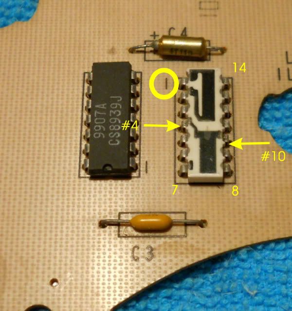
8.Clip leads #4 and #10 on the resistor pack: Here’s where you can use the small electronics side cutter. Be careful not to cut the wrong pins. (For reference, you can look at the other side, locate the ends of the capacitor located above the resistor pack and trace those traces to the resistor pack. Those are the leads to be clipped.)

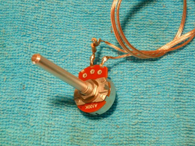
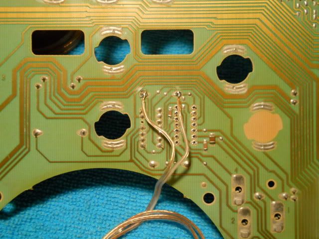
9.Attach the potentiometer across C4: The resistance that will ultimately calibrate the tach varies. The top of the bell curve ranges between 140k to 220k (according to Marc Haibeck as I recall, but mine came in at 240k) Note: I suggest getting a 100k Ω pot and a couple 100k Ω resistors. In some combination you will be able to range between 100k Ω and 300k Ω. In the picture you can see two 100k Ω resistors in series, coupled with the pot for a total variable resistance range of 200k Ω to 300k Ω.

The calibration jig attached across C4 on the "green side" of the PC board...

10.Reinstall cluster: Reinstall the PC board to the cluster and reinstall the cluster into the dash, making sure the cluster connector has fully engaged the cluster. Let the pot hang on the wiring where you’ll have access to it for calibration adjustment.
11.Set calibration: Connect your scanner (e.g. to the ALDL connector), reconnect the battery, and start the motor. Compare the scanner to the tach and adjust the pot so the tach matches the scanner at about the 2000 or 3000 rpm range.
Note: Sometimes the tach linearity is such that the tach may not track perfectly. That being the case, you can calibrate the tach to be accurate at the crucial (higher) rpm, but to do so you might have to reassemble the steering column etc in order to do a road test. However, according to those that have done this procedure some, the tracking error is not significant in most cases. And, because of lag – especially in the lower gears – a shift light is the way to get accurate shift rpm indication. It may be necessary to adjust the total resistance of the jig to get the tach into calibration.
12.Install the proper resistor in place of the pot: Disconnect the battery again. Remove cluster and the jig, taking care not to disturb the position of the pot stem, and read the resistance across the jig. Then select a resistor or combination of (series/parallel) resistors as needed to get as close as possible to the resistance measured across the jig and install the resistor(s) on the PC board, replacing the jig across C4. Use electrical tape to insulate the resistor wires from the PC board and arrange the resistor(s) to prevent the wires from touching anything else.
13.Reverse the disassembly procedure to reassemble the cluster, install it and return the dash and steering column to original configuration.
Credits go to Marc Haibeck with whom I consulted when I performed this procedure on my car.
Hope this helps!
P.
copyright 2012 All rights reserved